Trim and stretch

You can shorten or extend an unconnected end of a straight beam with a suitable trim plane. The trim plane can be selected from a main axis, from the face of another object, or freely defined in any angle. Most of these tools allow you to modify multiple beams at the same time.
X-axis, Y-axis, Z-axis
You can trim or stretch beams in positive or negative direction, using a plane whose normal is parallel to a main axis.
Do the following:
-
Select Structural tab > Beam group > Trim and stretch and then X-axis, Y-axis, or Z-axis.
-
Select the beam or beams that you want to modify, and press Enter to accept the selection. The trim plane is displayed in the work view.
-
If both ends of the beam are modifiable and the wrong end is currently selected, use the Reverse normal (O) context-menu command to select the other end.
-
Pick the point where you want the beam to end: the point should be inside the beam object if you want to trim the beam, and outside the beam object if you want to stretch the beam.
Tip: During this command, you can press Shift+C or F11 to lock the cursor to the centerline and to display the distance from each end, and then press Ctrl+Tab to edit the distance so that the cursor moves to the given point.
 Show/hide example
In this example, the selected (gray) beams are not of same length, but they will be stretched to the same target plane, to the opposing beam ends:

-
You can trim and stretch the beam multiple times, if needed.
-
Press Esc to exit the tool.
Define plane normal
You can trim or stretch beams with a user-defined trim plane.
Do the following:
-
Select Structural tab > Beam group > Trim and stretch > Define plane normal.
-
Select the beam or beams that you want to modify, and press Enter to accept the selection.
-
Use the context-menu commands to define how to trim or stretch the beam.
Show/hide details
-
Pick nearest face (F) – Select this to use the face of a nearby object as the trim plane.
-
Set origin (P) – Select this to pick a new origin for the trim plane.
Tip: During this command, you can press Shift+C or F11 to lock the cursor to the centerline and to display the distance from each end, and then press Ctrl+Tab to edit the distance so that the cursor moves to the given point.
-
Set normal (N) – Select this to define a new normal for the trim plane.
-
Reverse normal (O) – Select this to reverse the operative direction of the trim plane. That is, if both ends of the beam are modifiable and the wrong end is currently selected, this command selects the other end.
-
Set normal parallel to... – Select X axis, Y axis, or Z axis to align the normal with a main axis.
-
Plane through...
-
Point and normal (R)
-
Three points (V)
-
Nearest 2D line (Shift+F)
-
Point and two directions
-
-
-
Press Enter to accept the change.
-
You can trim and stretch the beam multiple times, if needed.
-
Press Esc to exit the tool.
Auto trim to nearest plane
You can trim or stretch a straight beam with the face of another object ("trimmer object"). The tool searches for a trimmer object from both sides of a user-defined point and selects the nearest suitable object, unless trimming would make the beam too short. If the tool does not find a trim plane, try adjusting the search radius.
Do the following:
-
Select Structural tab > Beam group > Trim and stretch > Auto trim to nearest plane.
-
You can use the Tool properties (P) context-menu command to open the Settings for Auto Trimmer dialog where you can adjust the settings of this tool.
Show/hide details
- Maximum search radius – Specifies the maximum search distance (mm) from the cursor to possible trim planes. Larger values provide a larger search range.
- Shortest trimmed length – Specifies a minimum length (mm) for the object to be trimmed. Beam will not be trimmed if trimming would make it shorter than this threshold value. The default value is 0 (no minimum length).

-
Move the cursor to where you want the tool to start searching for a trimmer object and press Space or click that location. If the tool found a trim plane, a preview of the modified beam is displayed in the work view. If a trim plane was not found, try pressing Space in a different location.
Show/hide example
This example shows how a slanted beam that is partly inside the floor can be stretched to the vertical beam nearby and trimmed to the surface of the floor.

-
Press Enter to accept the change.
Note: You can undo the change by pressing U, but there is no redo in this context. After exiting the tool you can use both Undo and Redo.
-
You can auto-trim other beams in the same way.
-
Press Enter or Esc to exit the tool.
Trim with miter
You can join two beams with a miter joint. The beams to be joined must use the same Catalog Part. The tool cannot be used on user-defined shapes.
The centerlines of the beams must intersect each other in the same plane, either physically (to trim the beams) or via projection (to stretch the beams). If the centerlines intersect but the edges or the axes do not, you are prompted whether to create the miter joint anyway.
Do the following:
-
Select Structural tab > Beam group > Trim and stretch > Trim with miter.
-
Click the first beam near the intended joint location and press Enter.
-
Click the second beam near the intended joint location and press Enter.
The two beams are joined with a miter joint.
Show/hide example
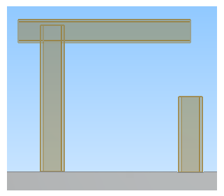
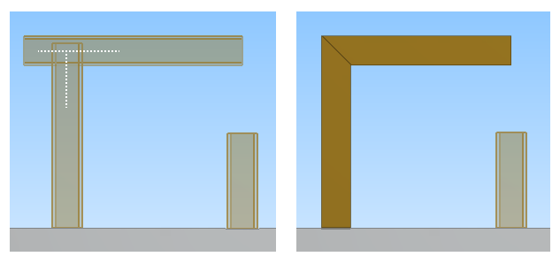
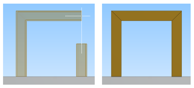
In this example, we have a horizontal beam which we want to connect to two vertical beams with miter joints.
First, we use the tool on the horizontal beam and the longer vertical beam. Their centerlines intersect, so the tool trims the beam ends to form the miter joint.
Then, we use the tool on the horizontal beam and the shorter vertical beam. Their projected centerlines intersect, so the tool stretches the shorter beam and trims the beam ends to form the miter joint.
-
You can continue using the tool to form as many miter joints as needed. Press Enter or Esc to exit the tool.